What We Do??
Step 1. Understanding PCB Firmware
Most hard drive circuit boards possess ROM, NV-RAM, or a controller chip that holds unique data required to access the hard drive system area. We call this data “PCB firmware”. If PCB firmware is missing or incorrect, there is no access to the hard drive, and no access to user data. Because of this, a simple circuit board swap will not make a faulty hard drive operational. It may be necessary to transfer the PCB firmware onto a new PCB.
In many cases, the ROM or NV-RAM chip is external, and can be physically transferred (soldered) onto a new circuit board. The PCB replacement guide explains how to do this yourself. Sometimes the PCB firmware is located on the controller chip, and without a professional BGA Rework Station, it is impossible to move that chip onto a new PCB. That same controller chip is often the problem in the original PCB. In these cases, a new chip must be reprogrammed with the correct PCB firmware (which Donor Drives can generate) with access to the original failed hard drive.
Step 2. Hard Drive Diagnostics
There are often many complications after a power surge, including a burned pre-amplifier, which is considered to be a mechanical failure related to head disk assembly
1. Check the hard drive cables. We always recommend using a toaster-like external enclosure for testing purposes. It is very easy to work with, and allows easy access to the hard drive while it operates, improving your ability to properly diagnose hard drive behavior.
2. Does your hard drive spin? Try to listen, touch it, or carefully lift it. If it makes a buzzing sound or a sound like it is trying to spin, the failure is most likely a spindle seizure and has nothing to do with the circuit board. If you hear a tick, or do not hear or feel any movement, the PCB is probably defective.
3. If the hard drive spins, try to decipher if it makes a quiet ticking or clicking sound. Does it spin for a while and then slow down? Such behavior indicates a head crash, and is rarely a PCB problem.
4. For a normally functioning hard drive that is not recognized by your computer, the issue could be anything, including circuit board failure, bad sectors, firmware, or any mechanical issue. Determine if the hard drive is recognized by BIOS with correct parameters. If it is, then it is probably a firmware or logical hard drive failure, not a circuit board defect.
5. Proceed with Donor Drives Circuit Board Swap Guide if you believe the PCB is faulty..
Step 3. Finding Replacement PCB
Finding a matching PCB for your hard drive can be difficult if the failed hard drive is rare; however, most of our customers can find a match by following our Donor PCB Matching Article.
Step 4. Brand-Specific Replacement
Western Digital
WD has 2 types of PCBs.
Type 1 has an 8-legged U12 ROM chip that must be swapped. See Step 4 of this Circuit Board Replacement Guide.
Type 2 has a missing U12 chip, and PCB firmware is stored in the big “M” Marvell Controller Chip. That chip can be transferred by a professional with a BGA Rework Station, or reprogrammed by Donor Drives.
Seagate
These hard drives have 2 architectures: Barracuda (older) and F3 (new generation).
Barracuda Architecture. These hard drives have a dot (.) in the firmware version (“3.CDA”, “8.01”, “3.03”, etc.). Most PCB swaps are simple (~85%). In the other 15%, a ROM chip must be swapped.
F3 Architecture. Hard drives have no dot (.) in the firmware version (“CC44”, “0005HPM1”, “SD01”, etc.). The 8-legged firmware chip will have a number starting with 25, and must be transferred to a new circuit board. See Step 4 of this Circuit Board Replacement Guide.
Note : If your hard drive has a new PCB recognized by incorrect parameters (such as wrong model, different SN, or incorrect firmware), a computer electronics professional or Donor Drives, LLC must swap the chip.
Toshiba
Most Toshiba boards have an 8-legged firmware chip that must be swapped. The chip will have a number starting with 25. See Step 4 of this Circuit Board Replacement Guide.
For some Toshiba families, the chip might be missing unique adaptive data stored in the large controller chip. That chip can be transferred by a professional with a BGA Rework Station, or reprogrammed by Donor Drives.
Hitachi and IBM
All Hitachi and IBM circuit boards have an 8-legged firmware chip that has a number starting with 25. See Step 4 of this Circuit Board Replacement Guide.
Maxtor
Adaptation service not required. A simple PCB replacement should work.
Samsung
Most of the time there is no need for adaptation service, but in some cases an 8-legged firmware chip (with a number starting with 25) must be transferred. See Step 4 of this Circuit Board Replacement Guide.
Fujitsu
PCB adaptation is not required, but occasionally, a firmware chip transfer is required. See Step 4 of this Circuit Board Replacement Guide.
Example of PCB Replacement
Make sure the PCB Replacement is relative and that PCB firmware needs to be transferred. Read our guide carefully for instructions.
Examine your hard drive circuit board to see if a ROM chip exists. The ROM is usually an 8-pin chip (4-pins on 2 sides) marked as U12 on Western Digital, or U6 or U5 on Hitachi. There is usually only one 8-pin chip on a hard drive circuit board. You will likely find a number starting with 25 on the chip. Western Digital USB-powered PCBs and some newer, large-capacity Hitachi hard drives have 2 ROM chips, so feel free to swap both.
If you aren't sure which chip to swap, contact us, and we will gladly help. For Western Digital PCBs, find a U12 white marking on the chip side of the circuit board. A missing chip in place of U12 would indicate that the PCB firmware is embedded in the controller chip. That chip can be transferred by a professional with a BGA Rework Station, or reprogrammed by Donor Drives.
Once the chip has been located, perform the PCB chip swap. If you do not feel comfortable doing it yourself, send it to us for PCB Adaptation Service, or contact a local professional. Do not trust this task to a stranger—this chip is vital for data access. An overheating ROM chip can result in significant damage and data loss.
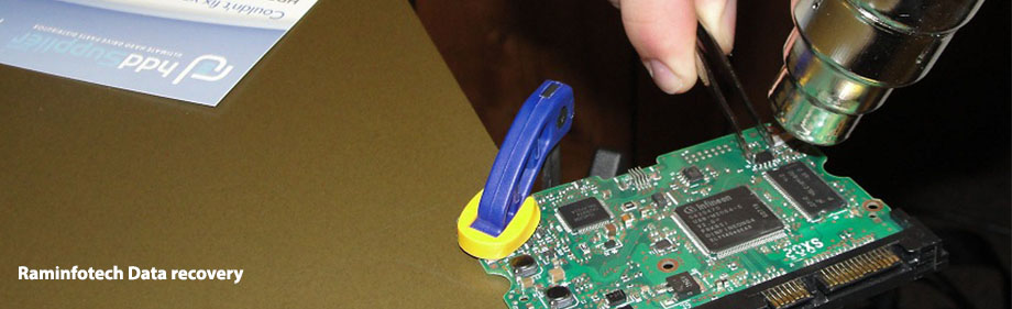
If you have soldering experience and the required tools, you can try this at your own risk. The required tools are: a hot air station or heat gun, metal tweezers, grip tool, and an optional soldering flux. Begin by strapping the new board to a table with the chip ready. You can apply tiny bits of soldering flux on all 8 pins of the chip if you want. Turn the heat gun or air station to high temperature and airflow settings. With one hand, hold the air-generating end a half-inch away from the chip for 10-15 seconds, while the other hand has the tweezers ready to remove the chip. Remove heat just a bit from the chip, and try to lift it with the tweezers. Do not tear the ROM chip from the PCB—it should come off with no force. Repeat this with the original ROM chip. Make sure to remember which side of the chip was on the board. There is a dot on both chips and PCBs in case you forget which side was on the board. Next, align the ROM chip from the old board on the new board. Apply heat for 10-12 seconds, remove heat, and cool the board. Make sure that the ROM chip sits tightly in place. Now you can try plugging in your hard drive.
If hard drive still does not spin:
1. There might be a different issue, such as a seized spindle.
2. For some modern WD drives, there could be a failed HDA preamplifier.
3. You haven’t fully soldered the chip. Check that all legs have a good connection to the PCB.
4. The chip was soldered on the wrong side.
5. The chip was damaged while soldering.
For any questions, comments or concerns – contact us at +91 70921 14411.